
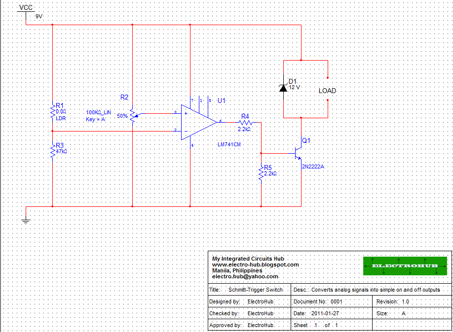
Today’s project is the Schmitt-Trigger Switch. This simple circuit converts analog signals from Light Dependent Resistors (light), or Thermistors (heat) into on and off signals which can activate relays, LED’s and other loads. The circuit works by using the 741 op-amp as a comparator to compare the voltages produced by the voltage divider networks created by R1 and R3 on pin 2, and potentiometer R2 on pin 3. When light (for LDR) or heat (for Thermistor) is applied, the sensor’s resistance changes and due to the voltage divider principle, the voltage that goes into pin 2 of the 741 changes. The potentiometer sets the reference voltage, which when matched by the voltage on pin 2, activates the op-amp, producing a small signal output. The output of the op-amp is too small to activate most loads, so it needs to be buffered up, which is done by the proceeding 2N2222A transistor. The voltage divider formed by R4 and R5 is used to limit the current and voltage that goes into the transistor’s base. The zener diode shunt to the load is used for relays to cut the reverse current produced by the coils and its value must equal the voltage rating of the relay.
Extra Notes:
1.) Transistor Q1 can be replaced by other small signal switching transistors. (BC547, 2N3906)
2.) LM741 produces larger outputs than UA741
3.) For reverse functions (light sensor to dark sensor), switch pins 2 and 3.
Troubleshooting:
Try to assemble the circuit in a breadboard first to make troubleshooting easier.
If the circuit doesn’t work,
1.) Check if pin connections on the IC are correct. Incorrect connections may damage the IC.
2.) Check if the connections on the transistor are correct. Connecting the transistor the other way around, will most likely damage it and in worse cases make it explode. The 2N2222A transistor has a pin configuration of Emitter-Base-Collector (looking at the flat side).
3.) Check the diode connection. It should be reverse biased, else most of the current will pass through it and not to the load.
4.) Check the resistance of the sensor. Remember, the circuit is on when the voltage produced in pin 2 matches or succeeds the voltage on pin 3. If the circuit is always on, or always off, you might need to change R3 (make sure R1 + R3 is less than R2 when you want the circuit to be off, and greater than R2 when you want it to be on).
5.) Check how much current is reaching the base of the transistor. Refer to the transistor data sheet to find out how much current is needed to activate it and change R4 depending on what you need.
6.) If it still doesn’t work, check if the supply voltage is properly connected. It’s a stupid mistake, but some still experience it…click to enlarge
No comments:
Post a Comment
Tell me what you think