Hi guys
I'm going to start a new segment here in Electrohub, and it will be called Money Matters.
Basically, everything about money. How to earn them, how to lose them, money trivias and stuff.
To start, let's have a "Money-making Triva"
Did you know???
Transmission Engineers in the middle east earn around 150,000 to 500,000 pesos a month? These are ECE's who work with Fiber Optic and Microwave communications system. Of course, not really a safe place for women, AND MEN WHO SHAVES THEIR BEARDS, but if you want big $$$ within a small period of time, that's the way to go.
Another job that involves electronic communications and pays 200,000-500,000 is the Cisco Certified stuff. If you can afford the time and money to enroll, it would also be a great investment.
As for me, I'll stick with one of the important lessons I learned in Engineering Economics, Perpetuity.
P = A / i
Calculate how much you need per month (A) and divide it by the interest rate you expect to get (i) and you'll know how much you'll need to invest (P).
For example, if you need 50,000 a month, and you find a bank or a company willing for 1% interest per month, then you only need to invest 5,000,000 pesos. If I would allow myself 10-15 years to save that much, then by the time I reach 40, I need not work nor go abroad, since I have a monthly 50,000 delivered to me.

Tuesday, August 9, 2011
Saturday, July 23, 2011
Use your num lock and scroll lock to show network activity
Most of the modern keyboards have three inbuilt LED lights for Num Lock,Caps Lock and Scroll Lock but they are idle for most of the time and we usually use only Caps Lock LED.Now we can use Num Lock LED and Scroll Lock LED to show networking activity.They will blink whenever you send or receive some data using internet.
Use this freeware utility called Network Lights only 75 kb in size and it doesn’t require any installation. ,
,*Special thanks to pctipstricks
Wednesday, July 13, 2011
ECE Reviewer
Hello again!
I made this quizzes for personal use but I decided to share it anyways. Its a reviewer for the subject General Engineering and Applied Sciences in our ECE board exam. This two modules contains objective questions about chemistry.
On my next update, I'll be uploading 2 two modules for physics.
Here are the links:
Module 1
------------------------------------------------
Module 2
------------------------------------------------
EDIT:
Visit this site instead: Brainjack
It is more updated and has more modules
...there is a reason why there's a password in the downloadable modules. For unlocked access, go to Brainjack.
Friday, May 20, 2011
The Fourth Element
As we all know, there are three fundamental passive circuit elements in electronics (Resistor, Capacitor, Inductor). Apparently, I just discovered that there are actually FOUR.
The fourth passive element is the Memristor. Its like a very small tube for current, where when current flows in one direction, the resistance of the Memristor increases and when current flows through in the opposite direction, the resistance decreases. Another feature of it is when the current stops, it retains its last resistance value.
I don't want to steal someone else's credit so for more information go here:
http://www.memristor.org
Tuesday, February 1, 2011
Tutorial Requests
If you guys want to request tutorials about anything that concerns electronics, email me at electro_hub@yahoo.com and I'll see if I can make one.
Give a man a pre-built electronics kit and he'll be able to create a project.
Teach a man electronics and he'll be able to start a career.
Give a man a pre-built electronics kit and he'll be able to create a project.
Teach a man electronics and he'll be able to start a career.
Friday, January 28, 2011
Schmitt-Trigger Switch
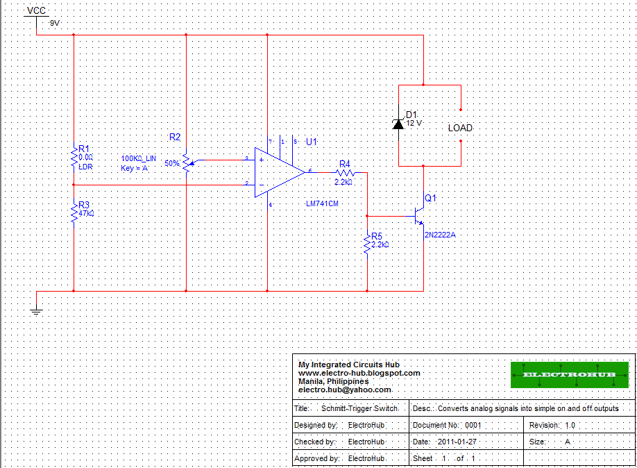
Today’s project is the Schmitt-Trigger Switch. This simple circuit converts analog signals from Light Dependent Resistors (light), or Thermistors (heat) into on and off signals which can activate relays, LED’s and other loads. The circuit works by using the 741 op-amp as a comparator to compare the voltages produced by the voltage divider networks created by R1 and R3 on pin 2, and potentiometer R2 on pin 3. When light (for LDR) or heat (for Thermistor) is applied, the sensor’s resistance changes and due to the voltage divider principle, the voltage that goes into pin 2 of the 741 changes. The potentiometer sets the reference voltage, which when matched by the voltage on pin 2, activates the op-amp, producing a small signal output. The output of the op-amp is too small to activate most loads, so it needs to be buffered up, which is done by the proceeding 2N2222A transistor. The voltage divider formed by R4 and R5 is used to limit the current and voltage that goes into the transistor’s base. The zener diode shunt to the load is used for relays to cut the reverse current produced by the coils and its value must equal the voltage rating of the relay.
Extra Notes:
1.) Transistor Q1 can be replaced by other small signal switching transistors. (BC547, 2N3906)
2.) LM741 produces larger outputs than UA741
3.) For reverse functions (light sensor to dark sensor), switch pins 2 and 3.
Troubleshooting:
Try to assemble the circuit in a breadboard first to make troubleshooting easier.
If the circuit doesn’t work,
1.) Check if pin connections on the IC are correct. Incorrect connections may damage the IC.
2.) Check if the connections on the transistor are correct. Connecting the transistor the other way around, will most likely damage it and in worse cases make it explode. The 2N2222A transistor has a pin configuration of Emitter-Base-Collector (looking at the flat side).
3.) Check the diode connection. It should be reverse biased, else most of the current will pass through it and not to the load.
4.) Check the resistance of the sensor. Remember, the circuit is on when the voltage produced in pin 2 matches or succeeds the voltage on pin 3. If the circuit is always on, or always off, you might need to change R3 (make sure R1 + R3 is less than R2 when you want the circuit to be off, and greater than R2 when you want it to be on).
5.) Check how much current is reaching the base of the transistor. Refer to the transistor data sheet to find out how much current is needed to activate it and change R4 depending on what you need.
6.) If it still doesn’t work, check if the supply voltage is properly connected. It’s a stupid mistake, but some still experience it…click to enlarge
Subscribe to:
Posts (Atom)